You want to join two shafts. What do you need? A coupler, of course. If the shafts don’t line up, you might consider an Oldham coupler. But what if the shafts are at a 90-degree angle to each other? Then you need a Hobson’s coupler. [Robert Murray-Smith] has the 3D printed hookup for you and a video that you can see below.
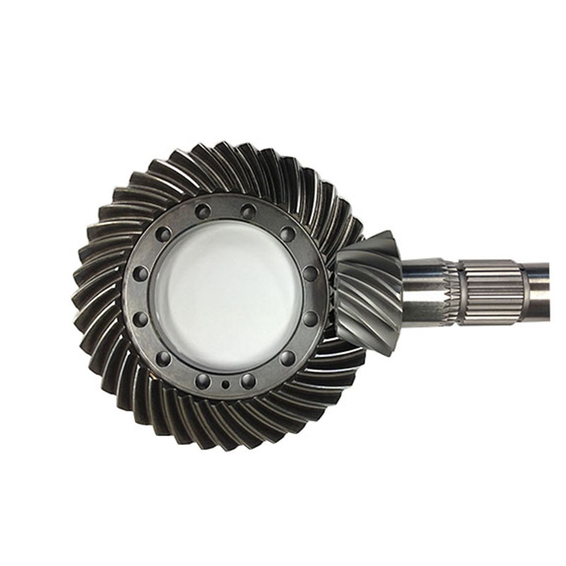
The part isn’t all 3D printed, though. You do need some bearings and steel rods. [Robert] proposes using this to couple a windmill’s blades to a generator, although we assume some loss is involved compared to a standard shaft. However, we’ve heard that the coupler, also called a Hobson’s joint or a stirrup joint, is actually pretty efficient. However, you rarely see these in practice because most applications will use a gear train employing a bevel gear. Parallel Shaft Helical Gearbox
While it may not be practical, the second video below shows an elbow engine that would look undeniably cool on your desk. By making some changes, you can create a Cardan joint which happens to be half of what you think of as a universal joint. The Hobson coupler and the Cardan joint seem to be made for each other, as you’ll see in the video.
We aren’t sure what we want to make with all these mechanisms, but as [Robert] points out, with new materials and techniques, these mechanisms might have a role to play in future designs, even though they have been mostly discarded.
There are, of course, many kinds of couplings. Then again, not all useful joints have to move.
That was pretty cool to watch, and made perfect sense as well.
Interesting. I always enjoy exploring unusual mechanical contraptions.
What about rotational velocity? If you feed it a stable rotational velocity, do you get a stable velocity out, or does it vary depending on the location and number of connecting links and their position within the rotation? My gut tells me it’s fixed, assuming perfect bearings, but…
I can also see it being susceptible to wear, since you have non-axial (bending) loads on the shafts and joints, and the sleeves receiving the shafts see both rotational and axial motion. Torque would only aggravate wear, and too much wear would result in catastrophic failure with flying bits; even more-so than a bevel gear, I expect.
Cool, and worth learning about, but too complex for production, I’m afraid.
All true, but not all rotational joints need continuous rotation. I can picture this being useful just for rotational position, for example, with more precision than a flexible shaft would provide.
Wear could be reduced by using either a brass sleeves or linear bearings. I’m more worried by wobbliness of the drum caused by the fact the supporting bearings are a bit far from it. Adding another bearing, around the drum, would be a solution for that…
The Malcolm Bricklin Rotary Vee engine was built on this principle, and i recall the Mechanic’s Illustrated article on it briefly addressing that, but i forget how
To keep stable rotational velocity you need a constant-velocity, or CV joint. Automotive engineers solved that particular problem for cars years ago. The Rzeppa joint is very commonly used as the outer joint, but there are other types.
Tom Stanton. Make a vtol plane using this!
Interesting but more complicated than 2 shafts with bevel gears at 90 deg. I wonder if the rotary to oscillating linear motion might be useful in a valve application, especially if you really needed desmo valving ?
It’s hard to see the advantage mechanically (I don’t how it’s better than bevel gears or a universal joint), but since it converts rotation to reciprocating motion over a short range, you could route wires or tubes through this without the need for a slip ring. So that’s cool.
You’d still need a slip ring at both ends of the joint, so i don’t really see how that could be advantageous..
If you needed a slip ring that’s at a 90 degree angle (or variable angle if we added the joints between the angled bars), what we could do is have the drums themselves be the slip rings we have the electrical contacts on, then have each one of the angled bars be a electrical connection itself to the corresponding slip ring on the other side. The number of bars to be electrical connections would be arbitrary as long as you can physically fit them in the space of the drums.
A normal slip-ring only really works on the one axis, which is fine for many if not most applications, but if you need to have a slip ring around a corner with massive space restrictions, could see such a arrangement being useful in niche applications. Could even add a spring in the middle of it to attach the two drums together and make the length be slightly variable as well to be more compliant with moving mechanisms without stressing cables constantly.
Without being a windmill designer, I think balancing the blade with the generator might be an important feature of the existing designs to avoid wear on the swivel connection. Hoisting a counterweight might be an alternative if the Hobson’s efficiency is spectacular, bit I’m guessing maintenance cost isn’t huge – you just need a crane if there’s not one already within, and pay some pittance of an hourly wage to a human. Definitely a cool contraption – Gromit would love it.
A Hobbit describes the Hobson!
A windmill would rotate out of wind as soon as the generator starts braking, so you would have to orient it inte wind and lock it down
Exactly, but EVEN WORSE. This is also why a simple 90 degree bevel gear boxes (which can be made to be immensely more efficient than a Hobson mechanism, and transmit immensely larger torques for the same general volume of the gear box (torque being a big issue for almost any size windmill)) are not used: even without the generator braking, it offers resistance to turning. To fight that resistance the rotation about the vertical axis if the windmill has to be fixed in place on the shaft or the whole thing will mostly want to spin in circles at the top of the tower and do very little turning of the the crankshaft of a vertically oriented generator at the base of the tower.
To have the power from windmill blades turn 90 degrees and go down it’s tower to a different location would require a fixed direction for the windmill to point, or a vastly more robust and probably notably more complicated active positioning system than any power production windmills currently have.
The Hobson mechanism is cute, but it uses the exact same principle to transmit torque around corners as any other gear mechanism, except with bars instead of teeth. For fixed angles it is awfully clunky and not volume or material efficient though. Even in regular situations where the power transmission is between two items that are fixed, and not regulating relative each other, it’s generally not a good choice. That’s why you don’t see them using things like a car with a transverse engine that has to turn the shaft output 90° to go to the rear wheels.
The Hobson mechanism gets a bit more interesting when the angle of transmission can vary though from directly in line down to 90°, and in some cases even a degree or two further. By taking the fellows 90° couplings and making them have a pin joint, the Hobson mechanism can can allow the input angle to change.
Even in those situations though, there are alternative mechanisms and even some gear sets that can allow some of that action. The one thing that is nice about the Hobson mechanism is that you don’t have to go through all the rigor of trying to cut gear teeth (a very tough thing to do well) to make one.
The turbine gearbox exists because the enormous torque from the rotating blades must be converted into high speed to run the generator. This chap is suggesting that the gearbox doesn’t need to be in the nacelle, but that just means an enormous, complicated, and heavy torque tube assembly would need to be run 150+ feet down the tower. In the past 20 years, gearboxes and crane availability have been the two largest challenges to the wind industry. If there were cheaper and easier ways of getting power to the ground, other than wires, someone would be doing it. Instead, the opposite is occurring, with switchgear and GSU transformers moving to the nacelle in some designs.
Does anyone know the date the Hobson’s joint was invented? I would guess it predates the invention of machine tools good enough to produce things like gears. But I can’t seem to find any sort of date of invention. This type of mechanism also seems like it would work pretty well in a 19th centure line shaft system for going around corners. But I can’t find any information to support this idea. It seems most shops that used this system did a good job of laying things out in parallel rows.
In terms of modern applications, I’d like to know if this has any advantage over a modern CV joint.
Please be kind and respectful to help make the comments section excellent. (Comment Policy)
This site uses Akismet to reduce spam. Learn how your comment data is processed.
Tandler Gearboxes By using our website and services, you expressly agree to the placement of our performance, functionality and advertising cookies. Learn more